Electrical Installation
Instructions for Electrical Connection
WARNING!
| • | The device must be installed only in compliance with the applicable regulations, otherwise it may not operate as intended. Proper installation should prevent water and dirt from entering the unit via the wires or conduit. |
| • | Before wiring the device, disconnect the power source supplying the device and ensure no hazardous atmosphere present; otherwise, electrical shock or ignition of a hazardous atmosphere could occur. |
| • | The power port must be powered by a regulated 24 VDC SELV/PELV power supply. |
| • | Install wiring in accordance with the electrical code of the country in use, the local authority having jurisdiction and these installation instructions, as applicable. |
| • | Do not make any connections to the device main board or junction box input, output, and relay connections while under power. Making connections under power could lead to electrical shock or ignition of a hazardous atmosphere. |
| • | Ensure that water and dirt are not able to enter the unit via the wire or conduit. If the unit is installed in a location known to be wet or damp, it is good practice to loop or bend the entry into the unit that prevents water incursion. |
| • | The internal grounding terminal located in the base of the transmitter enclosure must be used for equipment grounding. The external grounding terminal is only to be used as a supplemental bonding connection where local authorities permit or require such a connection. |
| • | Never remove or replace a Sensor while under power or when explosive hazards are present. |
Failure to follow these warnings can result in serious personal injury or death.
Shielded cable for measuring devices is recommended.
Always observe maximum cable lengths and cross-sections shown below.
Wiring Requirements
Refer to table on installation I/O drawing for wire lengths and sizes required for proper installation. The HART signal requires a load resistor across the signal.
The device sensor is provided with 4 wires for use. The table below shows the wire color definitions:
| Wire Color | Definition |
|---|---|
| Red | 24 VDC (DC +) |
| Yellow | 4 ~ 20 mA Source (SIG) |
| White | 0 VDC (DC -) |
| Green/Yellow | Earth Ground |
Power Supply Requirements
An external 24 VDC SELV/PELV power source is required. Use a high quality, DC power supply with low noise characteristics. See the diagram below for power supply and wiring details:
|
|
Power requirements |
|
|
Input voltage (at sensor) |
Nominal |
Maximum |
|
20 V DC |
220 mA |
350 mA |
|
24 V DC |
175 mA |
250 mA |
|
30 V DC |
130 mA |
200 mA |
Notice
The device signal cables shall be permanently connected (fixed) and protected against external damage, e.g. by:
| • | cable conducting, or |
| • | armouring, or |
| • | using separate multi-core cables, or |
| • | within an electrical enclosure, or |
| • | individually shielded with earth connection. |
Figure 8 Wiring Diagram
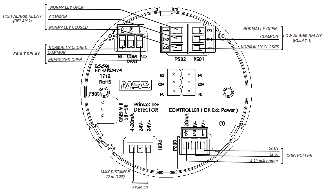
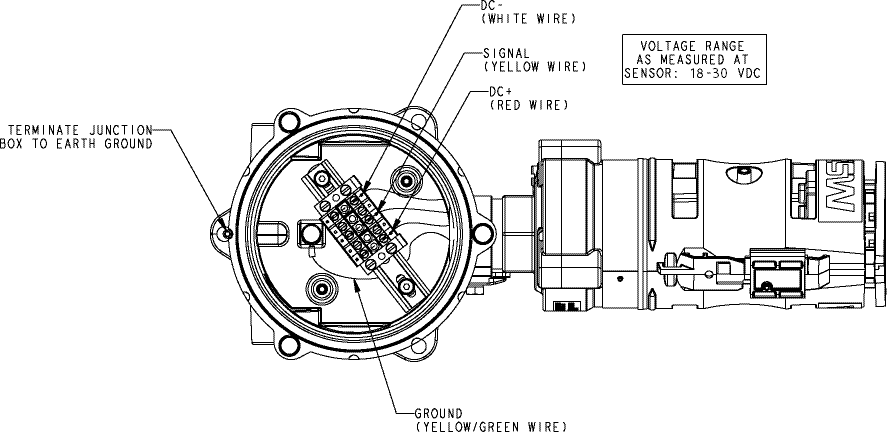
Figure 9 PrimaX IR Aluminum Junction Box with Sensor Connected
External Controllers
The device can be connected to any device capable of accepting a 4 - 20 mA sourcing analog signal. Ensure that the controller can read all signals. See www.MSAsafety.com for available controllers.
The HART output is intended to be used with digital control systems that are compatible with HCF Revision 7.0 protocol.